Selective Soldering Tips: Using the Machine for Rework

20130922-184705.jpgOk, I confess. Sometimes we do make mistakes. As much as I hate to admit it, it does happen. For example, we've seen headers not fully seated to the board. They're a little bit crooked or one edge is touching the PCB, while the other edge is so far up in the air that you can't even see the pin protruding through the other side of the board. Other times, you have an edge connector that needs to protrude through a cover panel and there's no room for play. The connector must be perfectly flat and perfectly square. If you find yourself in this situation, your selective soldering machine can be your best friend. Warning! On some machines, you may be required to bypass security features. Please consult your manufacturer before bypassing anything designed to protect you from a dangerous machine.

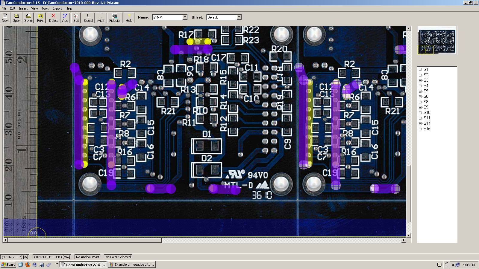
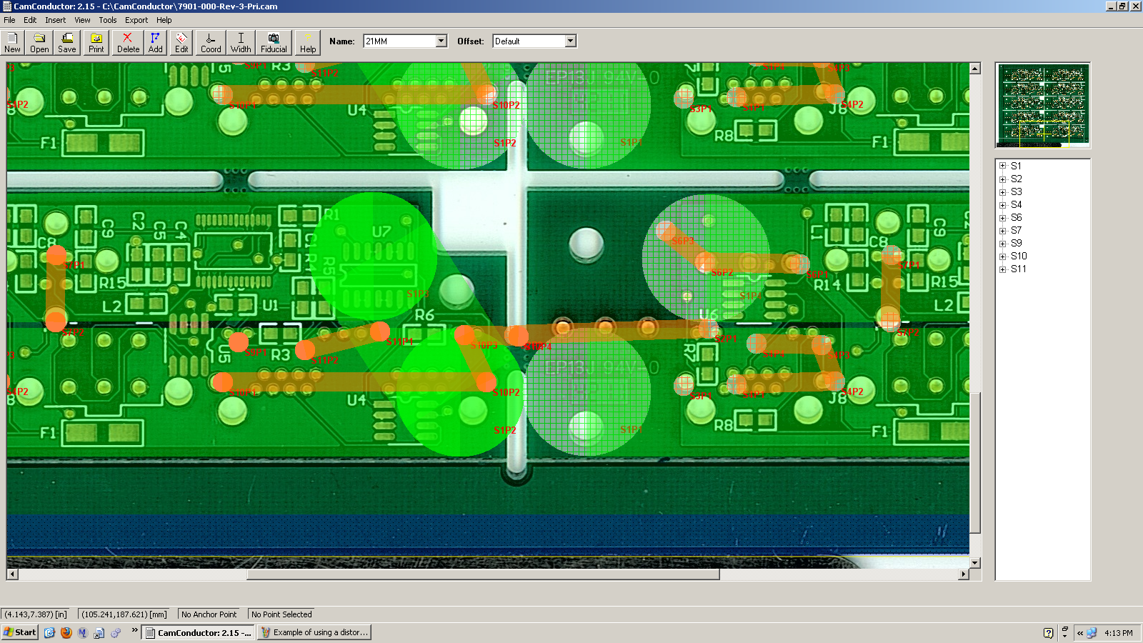
If your connector is larger than the size of your nozzle, you'll need to program the machine to "walk" back and forth over the pins of the connector, as seen in the image above. There's a limit to how long of a connector you could reasonably rework using this method. But we've been able to fix 2" long connectors on 4 layer boards. The key was to make sure the nozzle could dwell a little bit on the pins that were connected to ground.

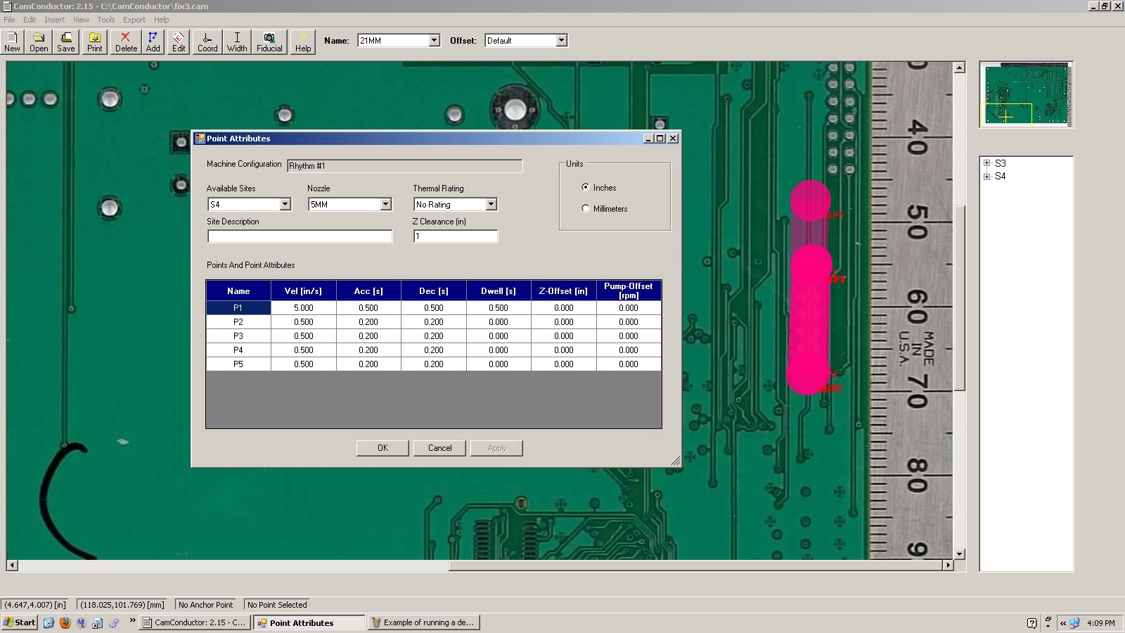
Every connector is different. Some connectors will become damaged with its much exposure to heat. The plastics just are not designed to handle it. For these connectors, we find it's best to just remove the entire connector and insert a brand new one. Other connectors however hold up well under the heat and you'll be able to apply slight pressure with your hand to push them back through the board. Be careful however, as a lot of times pushing the pins down will also push the solder down, and you'll have no top side filet.

Make sure to preheat the board. You don't want to hit this cold board with a bunch of molten solder. The thermal shock could shorten the lifetime of the assembly. So make sure it's nice and hot before you begin.

Selective Soldering Tips: Touching Surface Mount Components

This is just one article in a series of articles discussing tips and tricks for using a selective soldering machine. Here at Worthington Assembly Inc. we have a selective soldering machine manufactured by RPS Automation. Our particular model is a 2010 Rhythm model. These article are written by the same person who's used this machine every day for years. One of the beautiful things about selective soldering machines (vs. wave soldering machines) is that you can easily route around surface mount components that are mounted on the bottom side of the board. But it's not always that easy. For example, what happens when the board designer ran out of room and had to put surface mount components right next to the thru-hole components?

Well, believe it or not, you can actually safely make contact with surface mount components, so long as you reflow only one side of the component at a time. This requires that the design of the board has the surface mount components perpendicular to the plated thru-holes.

Example of touching surface mount parts

As you can see in the image above, the path of the nozzle crosses right over 9 surface mount components. The area where the nozzle makes contact with the component will reflow the solder that was deposited from solder paste, but the opposite side of the component will remain solid and hold the component in place. This can definitely make you a little nervous the first time you try it, but I assure you that component will stay put.

It would be a good idea to let your board designers know about this. Many designers would like to use every square centimeter of their board, and letting them know that they can put surface mount components very close to their plated thru-holes, so long as they are perpendicular to the holes, will certainly make them happy.

As always, if you have any questions, feel free to give me a call at (413) 624-6879 or send me an email at cdenney@worthingtonassembly.com.

Selective Soldering Tips: Negative Z to Adjust For Board Warp

This is just one article in a series of articles discussing tips and tricks for using a selective soldering machine. Here at Worthington Assembly Inc. we have a selective soldering machine manufactured by RPS Automation. Our particular model is a 2010 Rhythm model. These article are written by the same person who's used this machine every day for years. From time to time, we come cross assemblies that are quite large (16" x 16") and quite flexible. They may be a standard 0.062" board but they're loaded with a lot of large heavy parts. When you put a lot of heavy parts over a large area, it's a perfect recipe for board warpage.

We recently had a job with just these conditions. We have supports on our fixture to try to help with this phenomenon. They're aluminum bars that are self supporting on the fixture, with a spring loaded hook that tries to pull up a heavy board so that it remains flat and does not bow down. But even with these aluminum support bars, the board still wanted to bow down. The only solution was to adjust the height of the nozzle by changing the "Z-Height" in our program.

Example of negative z to adjust for board warp

This can be tricky though because if you lower your z-height all the way across the whole assembly, the areas that are well supported by the edges of the fixture or the aluminum bars may have very poor hole fill or just plain not get soldered at all. So you will need to identify areas on your assembly where the board is going to warp so far down that there's a risk of the leads of the components coming into contact with your nozzle. As you can see in the image above, we start out with no offset on our z-height. But as our path gets closer and closer to the center of the board, where we experience the worst warpage, we decrease our z-height by as much as 1.25mm. This may not sound like much, but we often find even a quarter millimeter can make a huge difference in consistent hole fill.

It's been suggested that we reduce the z-height over the whole assembly and just increase the pump speed. The reasoning is "If you just increase the pump speed, the solder will flow high enough to fill the plated holes properly." This may be true in some circumstances, but you'll be making compromises. In most cases, when your pump speed is too high, you'll experience more bridging, increased dross build up, not to mention that your contact surface area may increase considerably, potentially causing contact with adjacent surface mount components. Yes ladies and gentlemen, selective soldering is a process that will challenge your creativity.

As always, if you have any questions, feel free to give me a call at (413) 624-6879 or send me an email at cdenney@worthingtonassembly.com.

Selective Soldering Tips: Start Where You Finish

This is just one article in a series of articles discussing tips and tricks for using a selective soldering machine. Here at Worthington Assembly Inc. we have a selective soldering machine manufactured by RPS Automation. Our particular model is a 2010 Rhythm model. These article are written by the same person who's used this machine every day for years. Sometimes a person can populate a board much quicker than a machine can solder the board. So if you find that you're piling up boards waiting for the machine to finish, there are a number of different things you can do to reduce the throughput time. I will address just one of the ways with this article.

When drawing a path for the machine to follow, it's important to begin your next path as close to where your previous path stopped. If the machine needs to travel a long distance, criss-crossing back and forth around the board, you'll dramatically increase your cycle time and decrease efficiency.

Example of finishing where you start

I know this sounds obvious, but by being diligent with this practice, we have decreased cycle times by as much as 50%. How does this happen? Well, when you first program your board, you may not have thought about every little detail. Once you've run a couple of boards for the first time, you notice issues such as missing a part or coming into contact with a surface mount part on the bottom. So you go into the program and add a couple new paths. But each time you do this, you're adding complexity, and if you're adding complexity without considering where your machine needs to travel, you'll ultimately end up wasting a lot of time with the nozzle traveling all around the board with no thought put into it.

As always, if you have any questions, feel free to give me a call at (413) 624-6879 or send me an email at cdenney@worthingtonassembly.com.

Selective Soldering Tips: Drag Off Angle

This is just one article in a series of articles discussing tips and tricks for using a selective soldering machine. Here at Worthington Assembly Inc. we have a selective soldering machine manufactured by RPS Automation. Our particular model is a 2010 Rhythm model. These article are written by the same person who's used this machine every day for over a year. When soldering a double row header, or similar part, the solder can easily bridge at the end where the solder nozzle comes off. I don't know the technical term for this but I call it the drag off. There are multiple arguments for the way you can drag off the end of the double row header. The most common recommendation is to drag off at a 45 degree angle.

I don't necessarily agree with this. I found greater success dragging off parallel with the double row (in other words, straight). The key here is the speed you drag off at. The slower the better. (You can go too slow though, so be careful. If you go too slow you'll melt the header you're soldering.) More importantly, you need to use that same speed across the entire header. The trouble is, when the nozzle changes speeds or angles, it stutters. Not much though. It's almost imperceptible but if you look closely you'll see it. I don't know that this is necessarily what causes the bridging but I suspect it is. So what we do more often than not is to drag straight off the double row headers at 0.200" per second.

Selective Soldering Tips: Drag Off Angle

Now after explaining all of that, I must point this out. Sometimes it is still necessary to drag off at a 45 degree angle. Take a look at the above picture. You'll see 2 double row headers. The one on the left we drag off at a 45 degree angle. The one on the right we drag off straight.

You'll notice that on the double row header where we drag off at a 45 degree angle, the pivot point is right at the last 2 pins, while still barely touching the previous 2 pins. What's happening here, as best I can understand, is that we change all of the surface tension of the solder wave. We now have 4 pins all tugging at the solder as it's dragging off. This causes the solder to want to adhere just to the pins and not to fall back onto itself. That having been said, I've still had better success dragging off at a straight angle, without "stutter stepping" on the last four pins.

To sum up, try dragging off at a straight angle, making sure to go nice and slow over the whole double row header. We find 0.200" per second works best. If you get inconsistent results with that technique try dragging off at a 45 degree angle, making sure your pivot point is adhering to the last 4 pins to use them as tension against the solder bridging itself.

As always, if you have any questions, feel free to give me a call or send me an email.

Selective Soldering Tips: Dwelling for Better Hole Fill

This is just one article in a series of articles discussing tips and tricks for using a selective soldering machine. Here at Worthington Assembly Inc. we have a selective soldering machine manufactured by RPS Automation. Our particular model is a 2010 Rhythm model. These article are written by the same person who's used this machine every day for over a year. Some of the parts our customers ask us to solder can absorb a lot of heat. And I mean a LOT of heat. One particular part that we solder has 16 solder joints, is made completely of metal (not sure what but it seems like a tinned copper), and nearly every pin sits on an enormous ground plane. Not to mention, the holes are by no means oversized to make this any easier. Needless to say, it gave us some trouble.

We tried using a local spot preheat. This helped a little but at the end of the day, that solder still did not want to flow up through that ground plane. So we thought, why not just sit there with the nozzle. Turns out, that was the trick.

It's fairly simple really. Using RPS's software we just added an extra point at the four pins that absorbed the most heat. Then we just add a couple seconds of dwell at each point.

Selective Soldering Tips: Dwell for Hole Fill

Click here for the full size image

This worked like a charm. You can actually watch from the top of the machine as the solder climbs up the joint. It happens slowly, but once it makes it all the way through you can see a beautiful solder joint remains.

Dwelling on specific points will add to your cycle time obviously. But in an effort to make the best product possible, it's a small price to pay.

As always, if you have any questions, feel free to give me a call or send me an email.

Selective Soldering Tips: Using the Machine for Preheat

This is just one article in a series of articles discussing tips and tricks for using a selective soldering machine. Here at Worthington Assembly Inc. we have a selective soldering machine manufactured by RPS Automation. Our particular model is a 2010 Rhythm model. These article are written by the same person who's used this machine every day for over a year. Heat helps. Anytime you're soldering anything, the more heat the better. Even when soldering board by hand with a soldering iron, having the board a little warm before you start can help a lot, especially for boards with large ground planes.

One of the boards we run quite often here has just a couple of small connectors. It's a lead-free board but it was a real challenge to get it to solder consistently without bridging. We couldn't figure out what the issue was but after some experimentation, we discovered that heating the specific area we were about to solder helps for just a few seconds made all the difference.

As you can see in the image below, there is a small dot of orange in the middle of where we drag solder across the connector.

Selective Soldering Tip: Preheat using the Machine

Click here for the full size image

When we program the machine, we edit that specific point to dwell for about 3 seconds. We also add a negative z offset of about 5mm. What will happen is the machine will drive to that specific location, raise the nozzle as if about to solder there, but then never come into contact with the board. Heat will just pour out of the nozzle and the nitrogen shroud and get what whole area nice and warm. Right after that we just go ahead and drag solder across the connector and it comes out beautiful every single time. Since we've implemented this one change to this assembly, we have never had a single bridge. Ever.

Preheating is always helpful. We recommend using a hot air preheater before you even put the board inside the machine. But these are rather pricey. So why not just use your machine instead? (unless of course you need your machine to run as absolutely fast as possible)

As always, if you have any questions, feel free to give me a call or send me an email.

Selective Soldering Tips: Overlapping

This is just one article in a series of articles discussing tips and tricks for using a selective soldering machine. Here at Worthington Assembly Inc. we have a selective soldering machine manufactured by RPS Automation. Our particular model is a 2010 Rhythm model. These article are written by the same person who's used this machine every day for over a year. We do not own a wave soldering machine. We've never had a need for one. Most every circuit board we build has double sided surface mount and thru-hole, making wave soldering a non option. But sometimes we get circuit boards that are designed for wave soldering, so we have a technique for handling those.

We use our largest nozzle, which has an inner diameter of 8mm and an outer diameter of about 21mm. When we write our program, we overlap the path the nozzle will travel as seen in the image below.

Selective Soldering Tip - Overlapping

Click here for full size image

The reason we do this is because if we merely grazed the edge of the path we might get missed solder joints. This happens because the contact area, where the solder meets the circuit board, is not always consistent. It's affected by a number of things including your pump speed, the amount of solder in your solder pot, the flex in the board, etc (when a board is closer to the nozzle, the contact area gets much larger. Even a few tenths of a millimeter can make a big difference).  Overlapping the nozzle enables us to be more flexible. We don't have to keep such a close eye on the pump speed, or the solder level. And as our board heats up and bows, we don't have to worry about whether or not it's going to touch every solder point we need it to.

Overlapping doesn't have to be used only when substituting for a wave soldering machine. It can be used for a number of different applications. Be careful though because sometimes overlapping on areas where pads are too close or leads are too long can cause bridging.

We hope this helps. Please feel free to give me a call or send me an email.