So you've got a great idea and you want to bring it to market, but you don't know the first thing about hiring a manufacturer and working with them to get your product assembled? We are here to help. This is the first in a series of articles that we'll be writing that will help people learn how to work with us to get their product assembled.
So, what's a BOM? Well, you probably already know what a BOM is (Bill of Materials) but what are we specifically looking for from a BOM.
There are 3 vital pieces of information.
1. Reference Designator - this will be the location of your component. Something like R1 for resistors or U1 for IC's. You begin with a prefix and then assign them a unique number. Here are the common prefixes
- Capactiors "C"
- Connectors "J"
- Diodes "D"
- Displays "DISP"
- Ferrite Beads "FB"
- IC's "U"
- Inductors "L"
- LED's "LED"
- Modules "U"
- Oscillators (Crystals) "Y" or "X"
- Resistors "R"
- Resistor Networks "RN"
- Switches "SW"
- Test Points "TP"
- Transformers "T"
- Transistors "Q"
2. Manufacturer's Part Number - we'll need to know what part to put in the location you've specified. And what we are looking for is a specific manufacture's part number. Saying "100k ohm resistor" isn't quite enough information. Think for a second how many pieces of information need to be specified for just a resistor. Value, tolerance, size, wattage, composition, temperature coefficienct, and operating temperature. And that's just for resistors! It's just too much information than we'd like to decide for you. But an excellent resource is the Common Parts Library which WAi helped assemble in partnership with Octopart. We regularly keep these parts in stock and find them to be readily available and inexpensive compared to their alternatives.
3. Quantity - this is helpful for purchasing purposes. If you used a 1K resistor in 90 different locations, we'd rather not count those locations one by one to determine how many of that part number to buy. The quantity column will also help us double check our work. If we program our equipment and it tells us that there are 89 locations and you have a quantity of 90 specified, that will send up a red flag that there might be an issue.
There's plenty more information that some of our customers put in their BOM that are useful but inessential.
4. Line Items - this is handy for communicating back and forth. If we mention "There's a typo on line item 16" you'll know exactly where to look at your BOM for the issue.
5. Descriptions - Descriptions are really helpful. Internally, we use Digikey's descriptions as much as possible because it's formatted nicely and has all of the pertinent information. We can also use the description to make sure that your manufacturer's part number is correct. If your description says that it should be a 4.7k resistor and when we look up the manufacturer's part number and find that it's a 47k resistor, we can check with you to make sure you've chosen the correct part number. You'd be surprised how many mistakes we catch with this technique.
6. Datasheets - it's pretty useful to have a hyperlink to datasheets for components. Sometimes manufacturer's don't publicly release their datasheets (I'm looking at you Broadcom!) So if you provide us a link to datasheets it helps us speed up the process of programming your board. But don't stress about it. It's not necessary.
7. Hardware Details - providing a nice full description of a piece of off the shelf hardware is great. If you give us a part number from McMaster-Carr for a hex nut, that's great. But a good full description of the nut is even more valuable. Is it stainless steel, or galvanized? Is it 3/16", how many turns per inch, etc. When we have a nice full description we can confidently buy these parts from an alternative manufacturer. I love McMaster-Carr (seriously. I love McMaster-Carr) but they're expensive. And we can find hardware for far less money from other suppliers.
When you're done, here's what a BOM will more or less look like. They're generally formatted in a table that can be parsed by Excel or another spreadsheet program. CSV files and tab separated files work great too. We'd honestly prefer them over a proprietary format like Excel or OpenOffice.
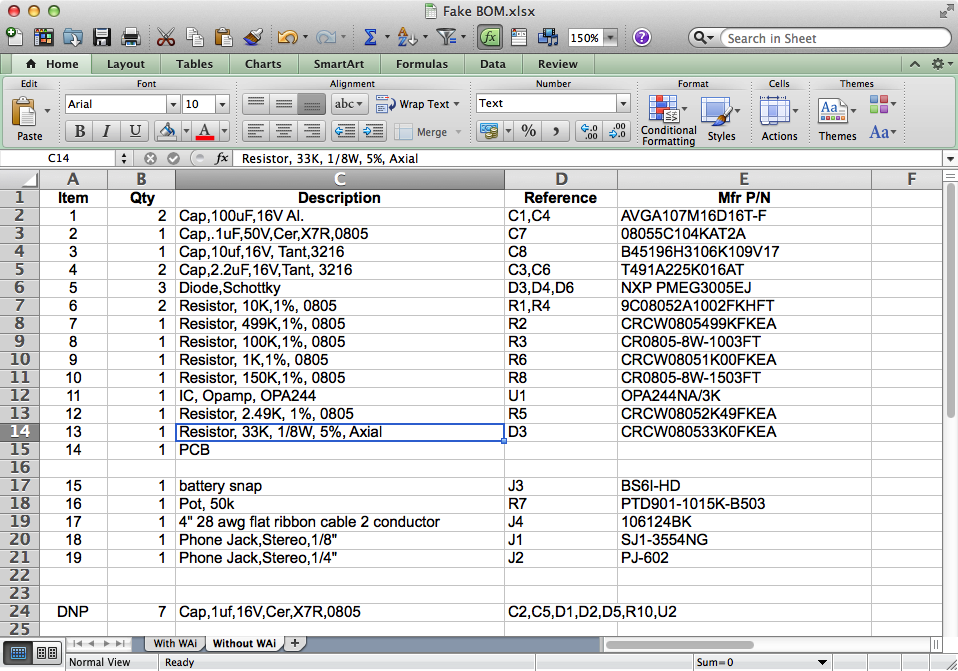
Example of a BOM (Bill Of Materials)
BOM's are vital. Will live and die by our customer's BOM. If you have any questions we'd love to hear from you. You can email me at cdenney@worthingtonassembly.com or give us a call at (413) 397-8260.